T104 Mechanical Pool Timer Switch, Weatherproof Plastic
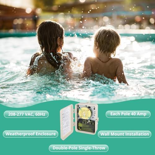
T104 Mechanical Pool Timer Switch, Weatherproof Plastic Enclosure, 208-277VAC 60Hz DPST, Indoor/Outdoor Install, for Pool Pump, Spa Equipment, Landscape Lighting, Outdoor Irrigatio
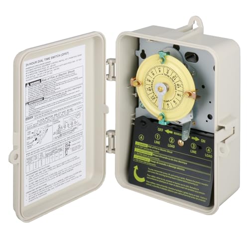
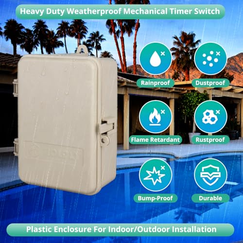
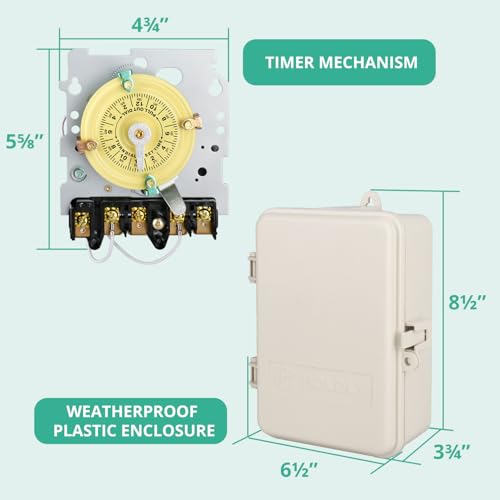
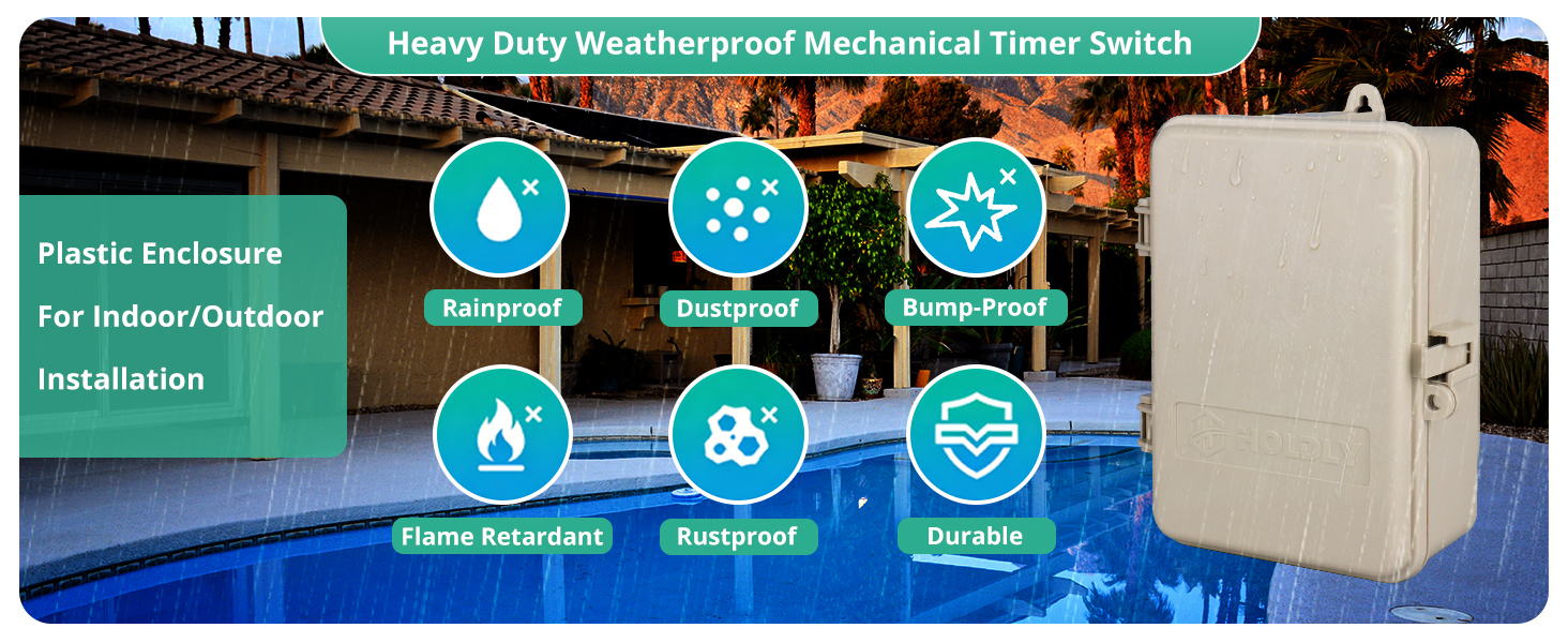
- Weatherproof Performance Plastic Enclosure, effectively resisting vertical rain, dust, and splashes to protect internal components from outdoor harsh environments. Compared to traditional metal enclosures, the lightweight corrosion-resistant beige plastic housing is more durable, rust-proof, and easy to install, avoiding the problem of metal rusting in poolside, humid or rainy outdoor scenarios.
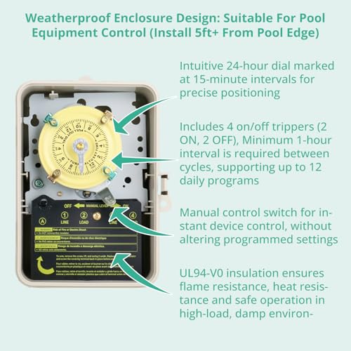
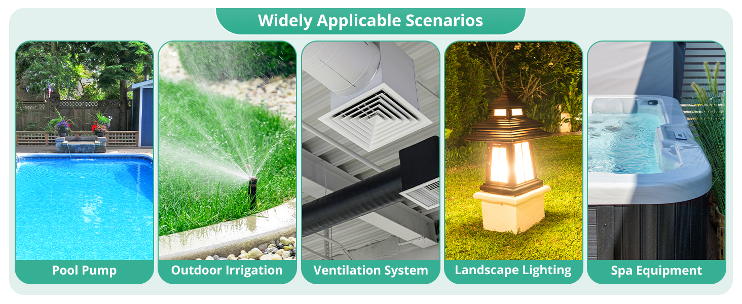
- Perfect for indoor and outdoor installation, widely used in poolside, garden, farm, patio, and commercial outdoor areas. It is specially suitable for controlling pool equipment (pumps, filters, heaters), SPA equipment (pumps, heaters), outdoor irrigation systems, greenhouse devices, landscape lighting, and other 208-277VAC heavy-duty outdoor electrical devices.
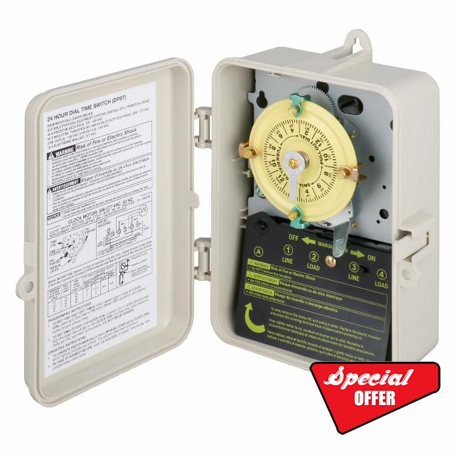
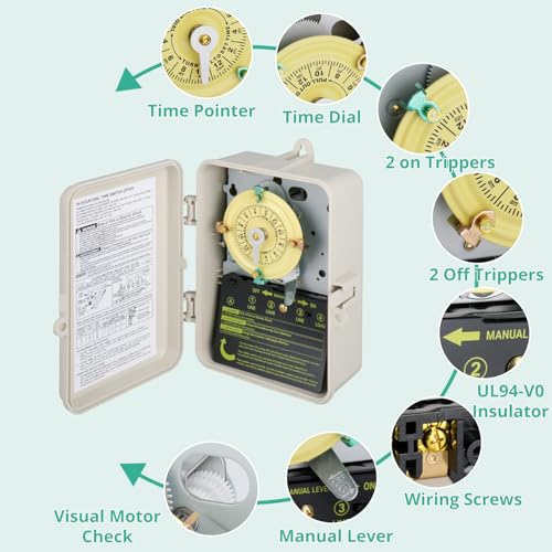
- Easy Operation & Flexible Timing Control – Intuitive 24-hour dial marked at 15-minute intervals for precise positioning. Includes 4 on/off trippers (2 ON, 2 OFF), supporting up to 12 daily programs with a minimum 1-hour interval between cycles. A manual control switch allows instant device control without altering programmed settings.
- Simple Installation & Strong Adaptability – Clearly marked terminals (live/load/neutral/ground) and a wiring diagram in the manual (photo old wiring for reference). Note: Fully reinsert the dial into the gear mechanism after setting the time.
- 5.Easy Maintenance & Mechanical Durability – Focus on the maintenance of mechanical gears and bearings: applying metal maintenance products to gears and bearings can significantly improve operational smoothness, effectively preventing and solving common issues such as jamming, lag, failure to start/shut down, and motor malfunction, and extending the timer’s service life.
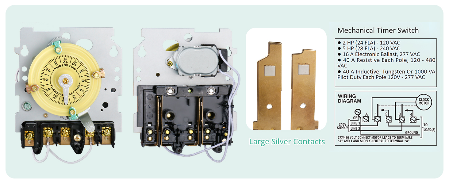
How do I wire the T104 timer switch?
Follow the diagram using insulated solid/stranded COPPER wire. Strip 1/2" insulation, insert ends under terminal plates. Tighten screws to ≥25 lb-in with a ≥3/16" screwdriver. Replace insulator before powering on.
How do I set the on/off schedule using the trippers on the T104 timer?
To set the ON and OFF times, hold the trippers against the edge of the CLOCK-DIAL, aligning them with the desired AM/PM times. Then, tighten the tripper screws firmly.
How do I manually override the T104 timer switch?
To operate the switch manually, move the MANUAL LEVER located below the CLOCK-DIAL either left or right as indicated by the arrows. This manual operation will not affect the next scheduled operation.
How do I set the current time on the T104 timer?
To set the time-of-day, pull the CLOCK-DIAL outward. Turn it in either direction to align the exact time-of-day (the current time when the switch is being put into operation) to the pointer. Do not move the pointer.
What is the max electrical load for the T104 switch?
40 AMP Resistive per pole at 120-480V AC
40 AMP Inductive or Tungsten or 1000 VA Pilot Duty per pole at 120V-277V AC
2 HP (24 FLA) at 120V AC
5 HP (28 FLA) at 240V AC

| SKU: | B0GLHN8TDJ |
| Brand: | Holdly |
| Colour: | Beige |
| Manufacture: | Holdly |
| Colour: | Beige |
Product description
How do I wire the T104 timer switch?
Follow the diagram using insulated solid/stranded COPPER wire. Strip 1/2″ insulation, insert ends under terminal plates. Tighten screws to ≥25 lb-in with a ≥3/16″ screwdriver. Replace insulator before powering on.
How do I set the on/off schedule using the trippers on the T104 timer?
To set the ON and OFF times, hold the trippers against the edge of the CLOCK-DIAL, aligning them with the desired AM/PM times. Then, tighten the tripper screws firmly.
How do I manually override the T104 timer switch?
To operate the switch manually, move the MANUAL LEVER located below the CLOCK-DIAL either left or right as indicated by the arrows. This manual operation will not affect the next scheduled operation.
How do I set the current time on the T104 timer?
To set the time-of-day, pull the CLOCK-DIAL outward. Turn it in either direction to align the exact time-of-day (the current time when the switch is being put into operation) to the pointer. Do not move the pointer.
What is the max electrical load for the T104 switch?
40 AMP Resistive per pole at 120-480V AC
40 AMP Inductive or Tungsten or 1000 VA Pilot Duty per pole at 120V-277V AC
2 HP (24 FLA) at 120V AC
5 HP (28 FLA) at 240V AC