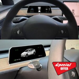
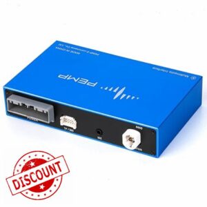
Fluke T5-1000 Open Jaw Electrical Tester with Continuity and Current Tester, 1000V
RRP PRICE: £176.40
SALE PRICE: £119.99
YOU SAVE: £56.41
SALE PRICE: £119.99
YOU SAVE: £56.41
- Reliable electrical tester automatically measures volts AC and volts DC with precise digital resolution Includes easy accurate OpenJaw current measurement
- Displays resistance to 1000 Ω
- Includes a continuity beeper for quick go/no-go tests
- All inputs are protected to EN61010-1 CAT III 1000 V CAT IV 600 V. UL CSA
- Max wire size 1/0 Thermoplastic, High Heat, Nylon Coated Cable
SKU: | B000LDKX62 |
Dimensions: | 20.3 x 5.1 x 3.1 cm; 300 Grams |
Model: | T5-1000 |
Batteries Included: | 2 AAA batteries required. (included) |
Manufacture: | Fluke |
Origin: | China |
From the manufacturer
When things are tight, reach for the Fluke T5
|
|
|
---|---|---|
Fixed jaws go where others can’tThe T5 can check current up to 100 A without breaking the circuit, simply by sliding its fixed jaws around the conductor. All the electrician needs to do is pull the cable away from the wall far enough to get it between the jaws. | Nothing needs to open or closeThe T5 works no matter how much moisture, mud or dirt it encounters on the cable. Moveable-jaw meters can prove troublesome when their jaw ends corrode, often rendering them difficult to use or entirely inoperative. This will never been a problem with the Fluke T5. | No extra hands neededThe T5 is one very compact instrument. Easily cradled in one hand, the T5 has a test lead slot in its back, making the meter an “extended handle” for the probe and leaving the user’s other hand free to place the other lead. It also features a large, easy-to-read digital display and a hold feature for checking the value away from the “reading” position. |
Applications
General applications
• Check if a circuit is live before beginning work • Check individual voltages (either ac or dc) • Determine component resistances up to 1000 ohms. • Check circuit continuity
Residential applications
• Measure loads on a branch circuit at a service panel • Measure the load side voltage of a circuit breaker or fuse • Map outlets to breakers
Industrial applications
• Check circuit loading at panelboards (including feeder cables, branch circuits, and neutrals) and the integrity of a grounding circuit • Check for leakage currents in branch circuits. When both a neutral and corresponding supply wire are placed in the T5’s jaws the reading should be zero. A reading other than zero indicates that leakage current is returning on another path and, therefore, a leaky load or poor insulation condition exists • Motor measurements including loading value, current balance and for troubleshooting control circuitry
Making electrical measurements with the T5
Voltage measurements
1. Turn the selector to the V. The meter automatically selects the correct internal circuitry depending on the type of voltage being measured. For volts dc and ac, the T5-600 is rated for 600 V CAT III and the T5-1000 is rated for 1,000 V CAT III or 600 V CAT IV.
2. Touch the probe tips to the circuit across the load or power source in parallel to the circuit. Either probe can be fitted into the back of the meter for easy two-handed operation.
3. Record the reading, making note of the units of measurement.
4. If you can’t read the display, press the HOLD button to freeze it, remove the meter from the live circuit, and then check the value.
Resistance measurements
1. Turn off power in the circuit to be tested.
2. Turn the selector to Ω.
3. Touch the probe tips across the designated component or portion of the circuit.
4. Record the reading.
Continuity
Continuity is a quick go/no-go resistance test that distinguishes between an open and closed circuit. The T5 continuity tester beeps when it detects a closed circuit (resistance less than 25 Ω) — no reading is required — and when it encounters an open circuit (resistance greater than 1000 Ω), “OL” appears in the display.
Current measurements
1. Turn the selector to A.
2. Place the jaws of the meter around the conductor. The conductor should be no larger than 0.5 in. diameter.
3. The conductor should pass through the sensor zone (noted by the circle at the base of the jaw opening) and parallel to the axis of the slotted opening. In a situation where checking for a “Live” conductor is more important than the absolute ampere reading, exact placement of the jaws around the conductor is less important.
4. View the reading. Note that the HOLD function can be used on all measurements as necessary.